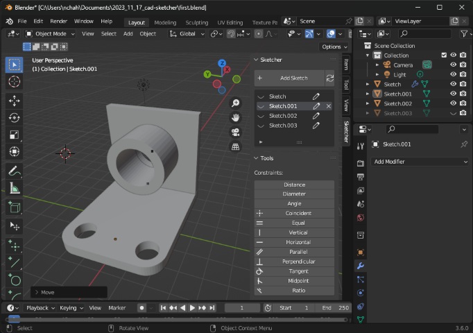
Blender: How to use Cad Sketcher
Introduction
CAD Sketcher, a fantastic tool that brings precise CAD-like functionalities into Blender for accurate modeling. This free and open-source add-on allows you to create 2D sketches defined by geometric constraints, convert them into editable meshes, and manipulate them using Blender’s geometry nodes and modifiers. It’s an awesome way to enhance your modeling workflow and create detailed designs. If you’re interested, I can guide you through the installation and basic steps to get started with CAD Sketcher in Blender!

Installing CAD sketcher
- Accessing CAD Sketcher:
- Visit the description section of the YouTube video where there’ll be a link to the official Gumroad page. plugin download link
- On the Gumroad page, you’ll find useful information. CAD Sketcher is entirely free, but if you wish to support the project, you can input an amount you’d like. If not, enter zero and click “I want this.”
- This will prompt a download of a zip file, which will be used for installation in Blender.
- Installation Process:
To install CAD Sketcher in Blender, follow these steps:
- Open Blender and navigate to Edit Preferences > Add-ons.
- Click on the Install button within the Add-ons section.
- Locate the downloaded zip file and install the add-on.
- After installation, in the search bar, type “CAD.” CAD Sketcher will be listed there. You can tick it for enabling the plugin.
- Proceed to install a solver module. Click on “Install from pip” and wait for a moment. If any issues arise during installation, a warning message will appear, indicating a need to restart Blender.
- Restart the blender anyways.
- Adjusting Preferences (Optional):
After successful installation, double-check the Preferences > Add-ons section to ensure CAD Sketcher is installed correctly.
- Adjust settings as per your preference. For instance:
- Modify entity size (up to 3).
- Adjust text size (up to 45).
- Change decimal precision and angle precision to 1.
- Customize theme colors if desired (e.g., setting it to a preferred shade like blue).
- Once adjustments are made, save the preferences.
- Adjust settings as per your preference. For instance:
Getting Started With CAD Modeling In Blender
- Access Sketcher and Create a Sketch Surface:
- Press ‘N’ to open the side menu in Blender. Or on the side, you can see a little arrow on the right.
- Look for a dropdown menu called “Sketcher” and select it.
- Click “Add Sketch” to create a new sketch. This action prompts various construction axis planes to appear, asking where you want to initiate the sketch. Choose a plane to start sketching on.
- Initiating Sketch and Applying Constraints:
- Enter the selected sketch plane.
- Consider moving the 3D cursor temporarily using Shift and right-click to place it elsewhere. (if you want to, when you remove this you will see the small point).
- Notice the presence of a small point, indicating a solved 2D point within the sketch.
- Creating a Basic Shape (Cube in this case):
- Use the rectangle tool to draw a shape by left-clicking and dragging.
- Horizontal and vertical constraints will automatically appear.
- To center the shape, use the line button to establish a construction line. Right-click to cancel the ongoing action.
- Convert the created line into a construction line.
- You can find the constraints in the sketcher sidebar, tools section. Press N to toggle the sidebar.
- Apply a midpoint constraint between the origin point and the construction line to center the shape.
- Adding Dimensions and Constraints:
- Set dimensions by specifying distances between points (e.g., 5 millimeters) within the sketch. Using the constraint feature.
- Manipulate constraints by clicking and dragging to delete or manually deleting constraints within the sketch.
- Fully Constraining the Sketch:
- Ensure all elements are equal to fully constrain the sketch.
- Utilize the converting options to turn the sketch into a mesh or a bezier. Opt for mesh conversion in this case.
- Click “Leave Sketch” once satisfied with the modifications made.
- Modifying the Resultant Mesh:
- Select the newly created face within the mesh.
- Add a solidify modifier to the selected face, setting it to a specific dimension (e.g., 4 millimeters).
- Solidfy modifier works like a extrude tool.
- Editing the Sketch Post-Modification:
- If desired, return to the sketch for further adjustments by clicking the pen icon.
- Change dimensions (e.g., altering from 5 millimeters to 2 millimeters) and observe the updates made in the mesh after leaving the sketch.
- Also, to draw on top of any surface, just add a workplane on that face. Sketch and solidify.
- How to extrude:
- Different sketches are different objects. To connect them together, you have to join them.
- Select one object, then use boolean modifier and select union and in the object section select the other object.
- Once applying the modifier, you can delete the extra objects.
- How to cut:
- It’s again to use same boolean modifier. Where you use the difference option
- Arraying
- For doing repeated structures, make an object, apply array modifier.
- You can select an offset and the number of objects you have to repeat.
- You can make use of union or difference boolean operation.
- Export the file as stl
- Always check that the modifiers are applied.
- Delete all the objects which are not in use.
- Check this in right panel: in scene collection. Only the object you care about should be there.
- Save the blend file.
- Then export the file as stl.
It is definitely not like solidworks. But I think it works more or less. And most importantly it is free.
References
you can check this video for how to install cad sketcher
you have this video to learn shortcuts and how it really works.